TAL 1 Strip Down and Restoration Guide - The TAL EQ Mount - by Astro-Baby
2 - Stripping and Rebuilding the TAL EQ Mount


This procedure will guide you in stripping, cleaning, lubricating and rebuilding the TAL EQ mount supplied with the TAL-1 telescope. This mount is also very
often supplied with the TAL 100R and TAL 100RS refractor.

The TAL EQ mount is a simple affair requiring only a few tools. The biggest problem you will encounter is the grease which is like tar It can be very hard to

remove. Take care with this and do not use chemicals as the paint finish is easily damaged. In this strip down I used a very powerful degreaser which
caused serious damage to the painted finish. In this case it made little difference as the mount was to be fully stripped and the paint removed for refinishing.

For this mount the plan was a complete refinish with new paints but you don't have to be that extreme.

Stage 1 - Stripping down the TAL EQ Mount - The Declination Axis
The TAL 100 EQ Mount Removing the declination nut removing the declination scale
Place the mount on a level surface covered by a soft towel or similar to protect the external finish. Remove the knurled nut on the end of the declination shaft. Remove the declination axis scale.
     
Removing the declination scale lock for the setting circle Removing the DEC fixing screw The DEC axis spindle being pulled from the DEC axis barrel
Remove the declination scale lock screw if desired. Unscrew the large crosshead screw on the declination axis. You can see some of the large paint damage that was evident on this mount in this picture. The declination axis spindle will now slide out of the declination barrel. The declination slow motion and clutch mechanism will now also fall free.
     
The DEC axis small nut Removing the DEC slowmotion mechanism Removing the spring pusher mechanism
Take care not to lose the small silver coloured square nut that sits on the declination axis. Remove the declination slow motion and clutch mechanism from the declination axis spindle. If you wish you can remove the pusher spring mechanism of the slow motion control using some mole grips or similar. You may wish to use a cloth between the grips and the spring pusher assembly to prevent the finish being damaged.
     
Removing the spring pusher mechanism The slow motion spring pusher components Removing the clutch / lock knob
The spring pusher can then simply be unscrewed. Here is the spring pusher mechanism showing the spring, the piston and the housing. On this mount these were almost solid with a black grease with the consistency of tar. The clutch / lock control for the declination is now removed.
     
The saddle plate set screw Unscrewing the saddle plate Removing the DEC axis set scale marker
The saddle plate for the telescope is held on with a thread and retained by a small set screw. Slacken this screw a few turns.... ....and now the saddle plate can be simply unscrewed from the declination spindle. The declination scale index marker can be removed using a small jewellers screwdriver if desired.
     
Stage 2 - Stripping down the TAL EQ Mount - The Right Ascension Axis
Removing the RA lock nut The RA lock nut removed Removing the RA scale
Unscrew the knurled nut behind the RA scale. Here is the nut removed. Remove the RA scale from the mount and store somewhere safe.
     
Removing the RA scale lock screw Removing the screw on the RA axis The RA spindle being removed
Remove the RA scale lock screw if desired. Remove the crosshead screw on the RA axis housing. The RA main mechanism will now simply pull free of the mount. The RA clutch and slow motion control will simply fall away at this point.
     
The small RA square nut close up of the small RA nut being removed removing the RA clutch lock
Be careful not to lose the small silver nut which sits on the RA axis spindle. Here is the small nut being removed. Remove the RA clutch lock.
   
Removing the RA slow motion spring pusher The RA spindle lock screw Removing the RA scale index marker.
If desired you can remove the RA slow motion spring pusher/piston assembly. It may require grips to unscrew initially. The RA axis spindle can be removed from the Declination barrel by removing this small set screw. The spindle will then unscrew. CAUTION the spindle is fitted very tightly and you risk damage to the mount by forcing these two units apart. Its not required for maintenance so you are advised to skip this step. The RA scale index marker can be removed using a small jewellers screwdriver if desired.
     
Removing the altitude lock lever The altitude lock lever removed The small washer under the altitide lock lever
The altitude lock handle can now be unwound from the mount. Here is the altitude lock handle fully removed. Remove the small washer under the lock handle.
     
The latest version of the TAL EQ mount altitude bolt The earlier verion of the TAL EQ mount altitude bolt Removing the screw on the altitude fitting
There are two versions of the altitude adjuster on TAL Mounts. This is the later version..... And this is the earlier version. Both versions require you to remove the lower screw first. Remove the lower screw on the altitude fitting
     
The altitide screw fitting removed Removing the main altitude bolt The altitude bolt being removed
Here is the screw fully removed. And now remove the three screws around the altitude spindle end. If this is a later TAL mount this will simply pull free at this point. With the three screws removed (for the earlier mount) the main altitude spindle will now pull free.
     
Note that the RA and DEC slo motion controls are slightly different The main components cleaned and ready for rework Small compnents bagged up ready for reassambly
Note that the RA and DEC axis are slightly different on this mount. I have two TAL EQ mounts and this is the only one that has this difference. Be aware of this when you rebuild. The main components of the TAL EQ mount laid out ready for cleaning and drying. Smaller components are bagged up awaiting rebuild after cleaning and drying.
     
Stage 3 - Cleaning, Stripping & Repainting
Degreasing the mounts main components Sopay water for all components of the TAL EQ mount The altitude casting during sanding down and cleaning.
The main components of the mount were left to degrease in a powerful degreasing agent.
Caution: This had the effect of damaging the paint. In this mounts case it didn't matter as it was going to be totally stripped and refinished.
After degreasing the main mount components were cleaned in warm soapy water before flushing with clean water and being left to dry. There are lots of steel components in a TAL mount which will very readily rust if not dried. The main altitude component after an initial run over with a wire brush. The black TAL finish is a very soft paint which will strip easily with hot water. Underneath on this component the mount had been painted with some kind of enamel glaze which needed quite vigorous treatment with a wire brush and emery cloth to remove.
     
SOme of the TAL EQ mount components partially stripped The main mount components after stripping and polishing Mount parts masked and ready for paint
The other main parts of the mount are aluminium with steel inserts. The mount I acquired was in a very poor state with corrosion and a lot of paint damage. These items were stripped easily with hot water and a wire brush. Here are the main mount components after stripping, brushing and polishing ready for their coat of Hammerite paint. Two parts of the mount masked up and ready for the first squirt with Hammerite spray paint. An earlier attempt with brush on paint was a disaster requiring the item to be restripped and prepared again.
     
Main mount elements after the first paint application The main mount components after repainting The clutch and slow motion controls, stripped and masked ready for painting
First part of the paint application. The mount is already starting to look better than even a factory fresh with a satin paint finish that will be very durable. The main mount components after repainting. These were sprayed with 5 coats of Hammerite Satin Black. The mount clutch and slow motion assemblies stripped and ready for painting. The slow motion controls are not easy to remove so were masked along with the metal faces that will come into contact with the rest of the mount.
     
The clutch and slow motion controls after painting The scope rings/mount cradhe during repainting Salt and vinegar make a good mic for cleaning anodised components
The clutch and slow motion controls after 3-4 coats of spray on Hammerite Satin Black. The scope rings/cradle assembly. I used the main axle element that fits onto the cradle as a support during spray paint (masked off of course). This was taken at the halfway stage. Anodized elements of the mount such as the RA and DEC retaining knobs were cleaned in a solution of salt and vinegar (half a glass of vinegar and 12 tsp of salt). Caution should be used when using this mix as its very acidic. Keep checking the parts in the solution. Approximately 15 minutes is enough to clean most metal components.
     
Stage 4 - Rebuilding The Mount
The components of the clutcha dn slow motion assemblies The spring pushers and pistons being greased Assembly of spring pusher piston assembly
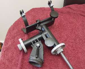
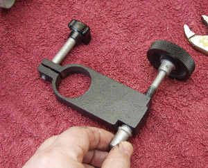
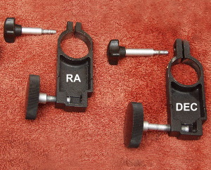
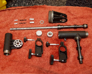
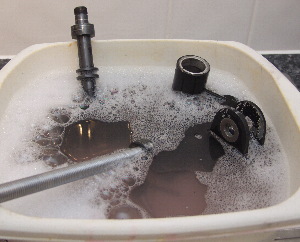
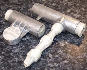
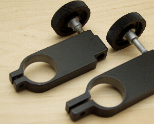
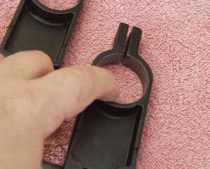
The first stage of rebuilding was the RA and DEC clutches and slow motions. Here are the parts laid out after cleaning and painting. 
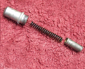
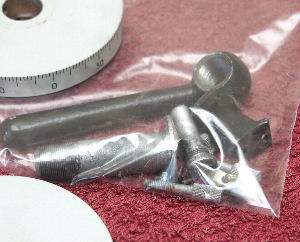
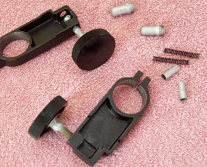
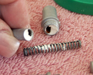
Pack the spring pusher assemblies with lithium grease and make sure the spring itself is well greased. 
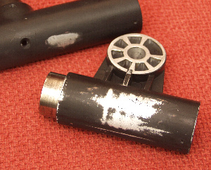
Insert the spring into the piston at one end and the cylinder at the other end.
 
Apring pusher being replaced into the slow motion control Tighetning down the spring pusher assembly regreasing the slow motion control spindles
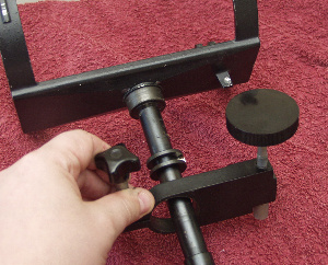
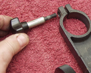
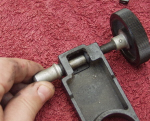
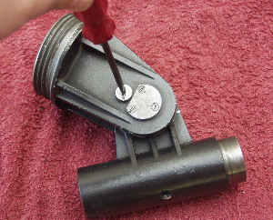
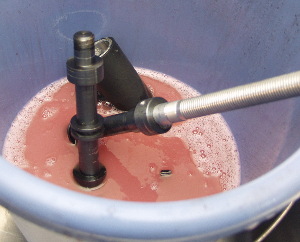
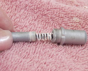
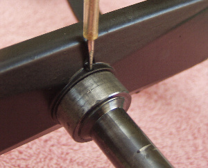
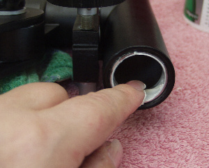
Now insert the assembled spring pusher and piston assembly. This is easier if you unwind the slow motion knob as far out as possible. 
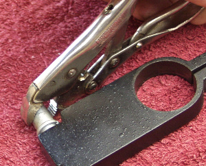
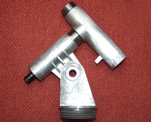
Tighten the spring assembly cylinder using some grips. Its best to place a soft cloth between the grips and the component for this to avoid the metal finish being damaged. 
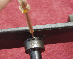
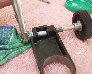
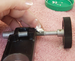
Finally dab a little grease onto the slow motion controls threads and wind it in to the mount to fully lubricate the threads.
 
Small grease application to the clutch faces Reaplecing the mount saddle plate to the DEC axis spindle Replacing the altitude housing/DEC housing
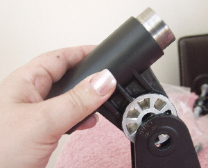
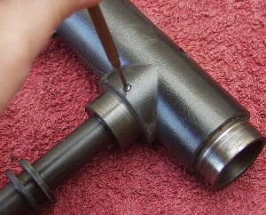
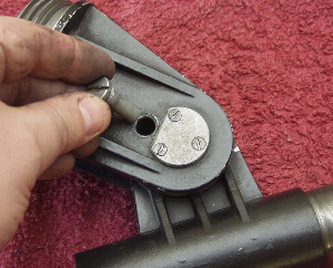
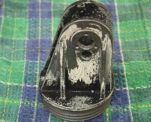
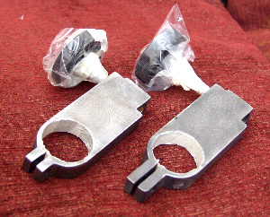
A tiny smear of grease should be added to the inner surfaces of the clutch assembly where it mates with the mount. Too much will cause the mount to slip when locked. No grease at all will make the mount bind. You need just very thin layer of grease here. 
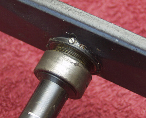
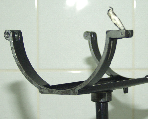
Now reassemble the mount cradle/saddle to the DEC spindle. Screw this into place and then tighten down the small lock screw. Do not overtighten this. Replace the main DEC housing into the mounts altitude fitting. Note that the DEC bearing faces were masked during painting.
 
Replacing the altitude bolt Fitting the retaining screws to the altitude bolt Replacing the altitude lock bolt
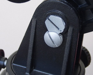
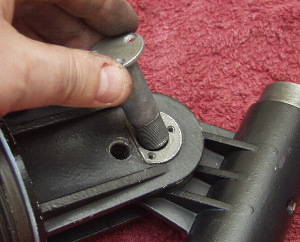
Replace the main altitude bearing spindle. Replace the three small screws in the altitude bearing spindle. Replace the lower nut into the altitude assembly.
 
Replacing the altitude locking handle washer Replacing the altitude handle/lever Replacing the DEC slow motion and clutch unit
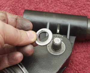
Replace the steel washer onto the main altitude spindle. Replace the altitude locking lever and tighten down. 
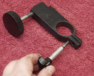
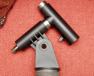
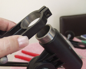
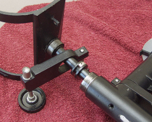
Replace the RA slow motion/clutch assembly over the DEC main housing.
 
Lubricating the DEC spindle and replacing the small curved nut Regreasing the DEC spindle Refitting the DEC slow motion control
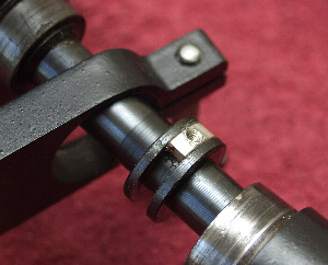
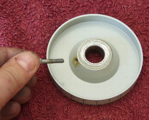
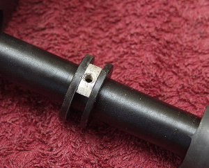
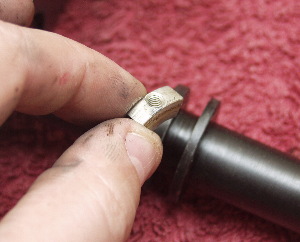
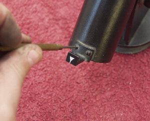
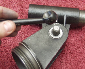
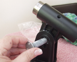
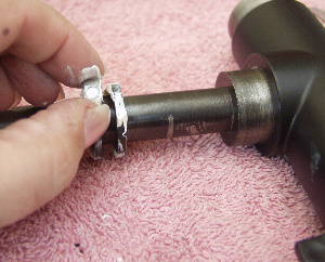
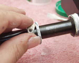
Replace the small square nut on the RA spindle between the two collars. In this picture this has been greased. Grease the RA spindle on its bearing faces. 
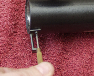
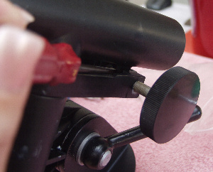
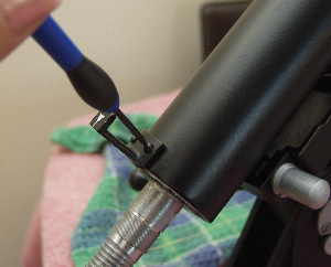
Now insert the RA spindle into the mount making sure that the tag on the RA casing mates up with between the spring pusher/piston and the slow motion control. You will find this easier by unwinding the slow motion control as far as possible and using a thin bladed screwdriver to press open the spring pusher.
 
Replacing the DEC lock screw Replacing the locking screw for the DEC slow motion assembly Greasing the DEC housing inner sleeve
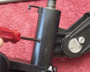
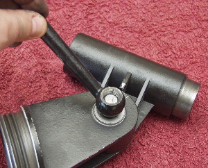
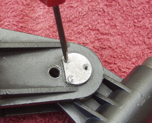
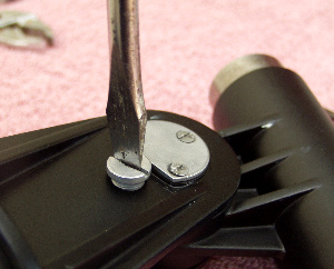
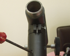
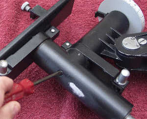
Replace and tighten down the screw that locates to the small square nut on the RA spindle. Replace the RA lock knob. Apply a small smear of grease to the inner face of the DEC housing.
 
Replacing the RA small curved nut and greasing the RA spindle Reassembly of the RA spindle into the housing Replacing the RA locking screw
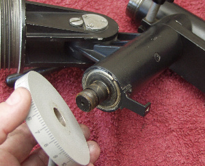
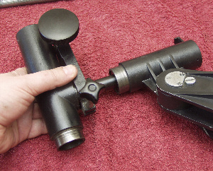
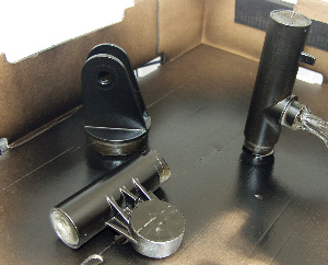
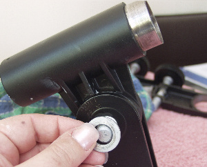
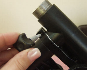
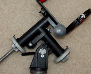
 Replace the small square nut on the DEC main spindle.  Place the DEC spindle into the DEC slow motion and clutch assembly and insert it into the mount. Make sure the spindle is greased on its bearing faces prior to assembly.
Note this picture was taken in the strip down phase as the rebuild picture was faulty.
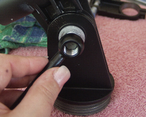
Use the same technique to fit the DEC slow motion and clutch as you used with the RA assembly to make sure the tab on the cradle is mated correctly to the slow motion controls. Now replace the screw that locates to the small square nut on the DEC spindle.
Note this picture was taken in the strip down phase as the rebuild picture was faulty.
     
Replacing the RA clutch lock bolt Replacing the index scale markers Replacing the DEC index scale
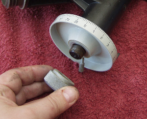
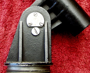
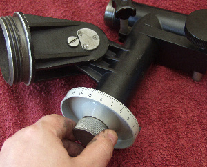
Replace the DEC lock knob. 
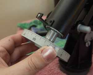
Replace the DEC index scale marker but do not tighten the screws down yet. Replace the DEC setting circle.
     
Replacing the DEC spindle main bolt Replaing the index markers Replacing the RA scale
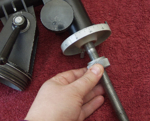
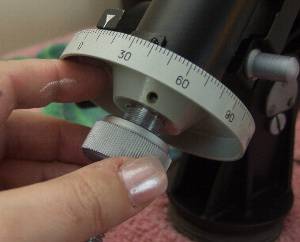
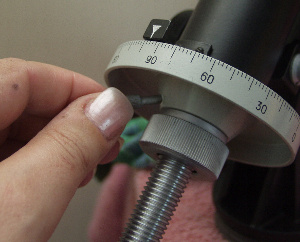
Replace the DEC knurled spindle main nut. Once this is done you can adjust the index marker so that it is close (but not in contact with) to the setting circle and tighten down the screws holding the index marker to the mount.  Replace the RA index scale marker. Replace the RA setting circle
     
Replacing the RA main bolt Replacing the setting circle lock bolts The completely restored and rebuilt TAL EQ Mount
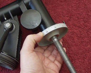
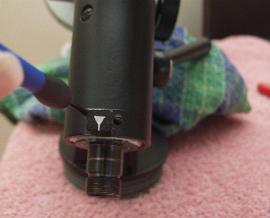
 Replace the RA knurled main spindle nut.
Note this picture was taken in the strip down phase as the rebuild picture was faulty.
Replace the setting circle locking nuts on both setting circles. The finished article looking better than new. New felts have been adding to the tube rings and the mount looks and works 100% better that before.
     
  BACK TO THE TAL RESTORATION GUIDE MAIN PAGE