 |
| 5 - Synta EQ6/Orion Atlas / Motor Engagement for RA and DEC
Axis |
This procedure will guide you
in setting up the EQ6/Atlas worm engagement and also aligning the motor gears
after the Declination and Right Ascension reassembly. These steps are best
carried out with the EQ6 head mounted onto
its tripod or some other type of stable base.
The worm setting
procedure - especially for the RA axis is very hit and miss and you will
probably need to go through it several time to find the 'sweet spot' where
there is both no play in the mount and the RA motor can turn the mount smoothly
with no motor stall or gear binding.
Play / tension in the mounts
axis are controlled by three elements. The worm carrier set screws, the end
float adjusters and, to a lesser extent, the motor engagement. If you are
having problems with a binding motor its best to slacken the motor away
altogether. Get a good setting on the worm carrier set screws and only then
tighten the motor back down. This symptom will show if all appears well UNTIL
the cap headed screws are tightened down. If this happens then the motor is
installed too tightly causing the motor gear and the worm gear to
bind. |
| |
| EQ6/Atlas Worm Engagement for DEC Axis |
 |
 |
 |
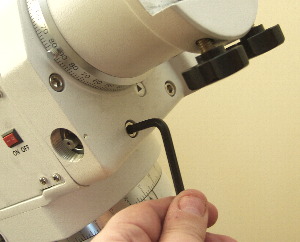
| Loosen the DEC axis worm carriers four large silver cap screws
JUST ENOUGH so that the small set screws can move the worm
carrier. |
Loosen the DEC worm carrier upper set
screw
and........... |
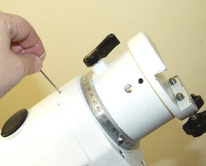
.....Tighten the lower DEC worm carrier set screw just enough so that
you can feel some play in the axis.
Note: You should loosen and tighten these
screws
by approximately 1 quarter of a
turn each time. |
| |
|
|
|
|
|
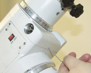
| Now loosen
the lower set screw and......... |
.......Tighten the upper set screw JUST UNTIL
ANY PLAY
STOPS.
Note: You should loosen and tighten these
screws
by approximately 1 quarter of a
turn each time. |
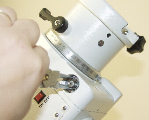
Now tighten down the DEC worm carrier cap headed screws. Work around
the screws clockwise tightening a little each time until
fully
tight. |
| |
|
|
 |
 |
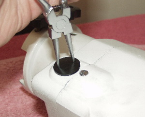 |
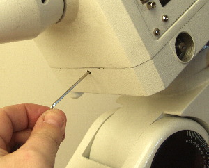
| The final
adjustment is to the worm end float adjuster. This is a slotted nut. It can be
turned using circlip pliers, snipe nosed pliers or two small screwdrivers with
fine blades. The worm float needs to be tight but not so tight that the mount
binds. Generally I start with the worm float being loose and then gradually
tighten it until the mount binds a little and then slacken it off. |
Run the mounts DEC motor a full 360' to make sure there is no
binding at any point in the cycle.
If binding occurs you will need to
readjust the set screws. This can be a long process to get the perfect balance
between no play in the axis and smooth motor running. |
Reinstall the worm end float cover. |
|
|
|
|
| EQ6/Atlas Worm Engagement for RA Axis |
 |
 |
 |
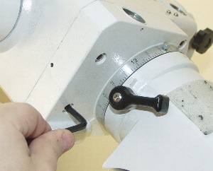
| Loosen the RA worm carriers four large silver cap screws JUST
ENOUGH so that the small set screws can move the worm carrier. |
Loosen the RA worm carrier upper set
screw
and...........
|
.....Tighten the RA worm carrier lower set screw just
enough so that you can feel some play in the axis.
Note: You should loosen and
tighten these screws
by approximately 1
quarter of a turn each time |
| |
|
|
|
|
|
| Now loosen the lower set screw and......... |
.......Tighten the upper set screw JUST UNTIL
ANY
PLAY STOPS.
Note: You should loosen and
tighten these screws
by approximately 1
quarter of a turn each time |
Now tighten down the RA worm carrier cap headed screws.
Work around the screws clockwise tightening a little each time until
fully
tight. |
| |
|
|
 |
 |
 |
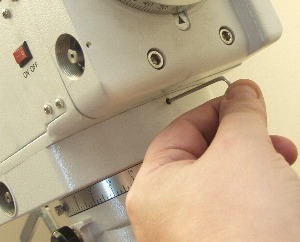
| The final adjustment is to the worm end float adjuster. This is a
slotted nut. It can be turned using circlip pliers, snipe nosed pliers or two
small screwdrivers with fine blades. The worm float needs to be tight but not
so tight that the mount binds. Generally I start with the worm float being
loose and then gradually tighten it until the mount binds a little and then
slacken it off. |
Run the mounts RA motor a full 360' to make sure there
is no binding at any point in the cycle.
If binding occurs you will need to
readjust the set screws. This can be a long process to get the perfect balance
between no play in the axis and smooth motor running. |
Reinstall the worm end float cover. |
|
|
|
 |
 |
 |
If you are
only adjusting the worms on the EQ6 and are curious about how they work these
diagrams may help.
The set screws that you adjust bear againts two brass
blocks inside the mount under the worm carriers. The diagram above shows the
layout of the running gear inside the worm carrier. |
As you tighten the lower set screw the screw pushes against the block
thats secured to the mount. The set screw forms part of the worm carrier so as
you tighten the set screw (small blue arrow) the carrier is forced towards the
block (large blue arrow). In this case as you tighten the lower set screw the
worm is pulled away from the ring gear. This is the firts step in tun ing the
worm gear. |
As you tighten the upper set screw (small red arrow) the same process
occurs. The worm carrier is forced backwards towards the set screw (large red
arrow) and as you can see the worm itself is now pulled into contact with the
ring gear.
Its
essential when you play with the set screws that you always slacken the
opposing set screw off to prevent damage to the mount. |
| |
|
|
|
| EQ6/Atlas Motor Gear Removal and Adjustment |
As part of the
complete strip down guide I removed the motors and the motor control board from
this mount. This isn't really necessary for a conventional strip down but given
the mounts history of poor periodic error performance I needed to make sure the
motor gear was OK and that there were no problems.
In fact the motor
gear, like the rest of the mount, was suffering almost no lubrication. This
step can be necessary after a rebuild to reseat the motors. Cleaning up the
over painting on the worm carriers can reduce the distance between the gears
enough to cause the gear works to become too tight with the result that the
motors will bind and stall.
|
 |
 |
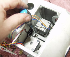 |
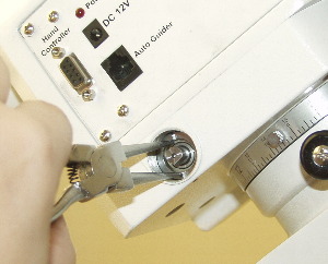
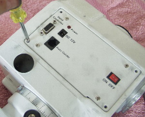
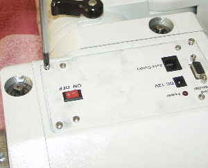
| Remove the 4 outer screws around the EQ6/Atlas control
panel. |
Gently pull the control panel away, revealing the motor control
board. You can either disconnect the motors from the main board or leave alone
and extract all of the motors and control board as one unit.
CAUTION Take suitable
static precautions as the motor boards on these mounts are reputed to be very
fragile. |
Remove the two screws from each motor and be careful not to lose the
washers. |
| |
|
|
 |
 |
 |
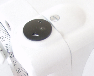
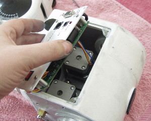
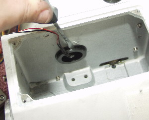
| Gently ease the motor away and extract it. You will need to do this
for each motor. |
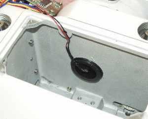
Using a fine bladed screwdriver prise the polarscope illuminator away
from the mount. |
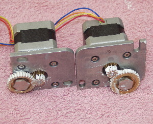
The motors on this mount showed little lubrication. Their gears were
cleaned with a little alcohol on a cotton bud and then regreased using white
lithium grease. |
| |
|
|
 |
 |
 |
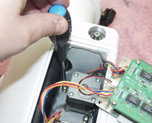
| Reinstall the motors. Because the gearworks are hidden in the EQ6 at
this stage its not possible to gauge pressure on the motors. I would advise
gentle pressure against the motor towards the worm gear as you replace the
fixing screws for the motor. |
Replace the polarscope illuminator. |
Replace the motor control board/control panel and replace the outer
screws. |
| |
|
|
|
|
| EQ6/Atlas Altitude Movement |
The mount used for the
rebuild in this guide had no problems with its altitude bearings. Altitude
bearing problems will show when the mount will rock in its altitude no matter
how tight the altitude adjusters are locked down.
As the process of adjusting
these can be destructive to the mounts trim and no problems were observed with
this mount these were left alone. Consult the HEQ5 guide
HERE for instructions as to
how to adjust these. The HEQ5 and EQ6 are similar in this
respect.
|
| Back to the EQ6/Atlas Rebuild Guide
Main Page |
| |
|
|