 |
| 5 - Synta HEQ5 -Worm / Motor Engagement for RA and DEC
Axis |
This procedure will guide you
in setting up the HEQ5 worm engagment and also aligning the motor gears after
the Declination and Right Ascension reassmbly. These steps are best carried out
with the HEQ5 head mounted onto its tripod
or some other type of stable base.
The worm setting procedure -
especially for the RA axis is very hit and miss and you will probably need to
go through it several time to find the 'sweet spot' where there is both no play
in the mount and the RA motor can turn the mount smoothly with no motor stall
or gear binding. |
| |
| Worm Engagement for DEC
Axis |
 |
 |
 |
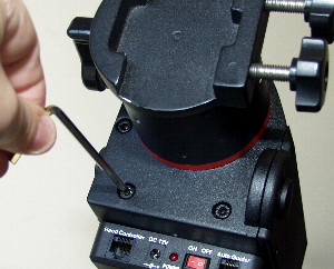
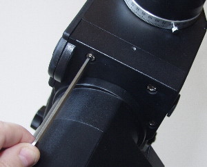
| Loosen the DEC axis worm carrier three large silver cap screws
JUST ENOUGH so that the small set screws can move the worm
carrier. |
Loosen the DEC worm carrier upper set
screw
and........... |
.....Tighten the lower DEC worm carrier set screw just enough so that
you can feel some play in the axis.
Note: You should loosen and tighten these
screws
by approximately 1 quarter of a
turn each time. |
| |
|
|
|
|
|
| Now loosen
the lower set screw and......... |
.......Tighten the upper set screw JUST UNTIL
ANY PLAY
STOPS.
Note: You should loosen and tighten these
screws
by approximately 1 quarter of a
turn each time. |
Now tighten down the DEC worm carrier cap headed screws. Work around
the screws clockwise tighetning a little each time until
fully
tight. |
| |
|
|
 |
 |
| At this point return to the DEC Assembly Guide or simply replace the Motor
Cover. |
|
| Remove the
motor cover and check that the motor gears can easily move the axis by manually turning them by hand or using the
mounts motors. |
Run the mounts DEC motor a full 360' to make sure there is no
binding at any point in the cycle.
If binding occurs you will need to
readjust the set screws. This can be a long process to get the perfect balance
between no play in the axis and smooth motor running. |
|
| |
|
|
|
| Worm Engagement for RA
Axis |
 |
 |
 |
| Loosen the RA worm carriers three large silver cap screws JUST
ENOUGH so that the small set screws can move the worm carrier. |
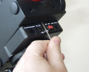
Loosen the RA worm carrier upper set
screw
and...........
Note:
You will have to remove the power panel to get axis to the upper RA set screw.
The panel is retained by two Phillips screws. |
.....Tighten the RA worm carrier lower set screw just enough so that
you can feel some play in the axis.
Note: You should loosen and
tighten these screws
by approximately 1
quarter of a turn each time |
| |
|
|
|
|
|
| Now loosen the lower set screw and......... |
.......Tighten the upper set screw JUST UNTIL
ANY PLAY
STOPS.
Note: You should loosen and tighten these
screws
by approximately 1 quarter of a
turn each time |
Now tighten down the RA worm carrier cap headed screws. Work around
the screws clockwise tighetning a little each time until
fully
tight. |
| |
|
|
 |
 |
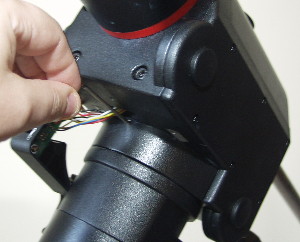
At this point return to the RA Assembly Guide or simply replace the motor cover
and the power panel using the Phillips screws.
Take care when replacing the power panel
not to trap any wires. |
|
| Remove the motor cover and check that the motor gears can easily move
the axis by manually turning them by hand
or using the mounts motors. |
Run the mounts RA motor a full 360' to make sure there is no
binding at any point in the cycle.
If binding occurs you will need to
readjust the set screws. This can be a long process to get the perfect balance
between no play in the axis and smooth motor running. |
|
| |
|
|
|
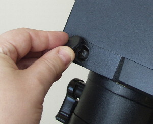
| End Float
Adjustment |
 |
 |
|
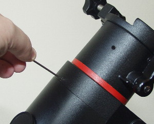
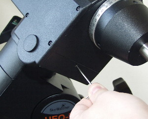
Remove the soft rubber covers to reveal the end
of the worm shaft
and float adjuster. |
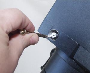
Loosen the float adjusted using either a small
jewellers
screwdriver or a small allen key to locate into the adjusters slots. You
should feel the some play in the axis. Now tighten the float adjuster down
until any play disappears. The float adjuster should be in contact with the
worm bearing but not overtight or else the axis will 'bind' |
Replace the rubber worm float covers |
|
|
|
|
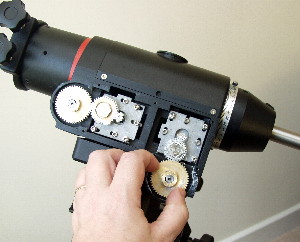
| Motor Gear
Adjustment |
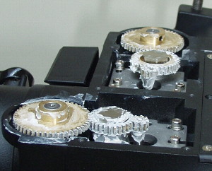 |
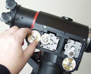
The
HEQ5 Motor gears should all be flush with each other as shown in the picture to
the left. The gears should be closely fitted but not pressed together too tight
to prevent excessive gear wear.
REMEMBER one of the
gear set screws must be against the flat of the worm spindle.
The
gears in my mount are liberally coated with Lithium grease to reduce wear and
also to muffle running noise. |
|
|
|
|
|
|
| Back to the main page
HERE |
| |
|
|