TAL 1 Restiration and Strip Down Guide - The OTA - by Astro-Baby
3 - Stripping Down and Rebuilding the TAL-1 Optical Tube Assembly (OTA)

The TAL-1 Optical Tube Assembly (OTA) is relatively straightforward to strip down. Older units seem to show a lack of general care in the original assembly
work and of two I have worekd on both suffered from stripped threads and general poor finsih internally.

This can be corrected easily by replacing screws with stripped threads. Almost all of the threads are M4 on the OTA. The rebuild is straightforward enough

but as ever exercise care with optical components.

Stage 1 - Tube Strip Down and Mirror Removal
Removing the three screws that hold the mirror and rear plate to the telescope Removing the rear plate The rear plate and mirror cell being removed from the tube
Remove the three screws that hold the telescope rear plate into the tube. CAUTION - do not undo these screws without either supporting the rear plate or having the telescope facing downwards. The rear element contains the mirror and is quite heavy and you don't want it dropped onto the floor. 
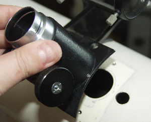
With the three screws removed and the telescope tube facing slightly downwards you can now VERY GENTLY remove the rear cell of the telescope. Here is the rear cell removed showing the mirror cell and within it the primary mirror.
     
The TAL 1 Primary mirror assembly Removing the mirror cell from the rear plate Removing the main collimating screws and mirror cell retainers
The face of the primary mirror. On this scope the mirror was very dirty and covered in dust. To remove the mirror cell and the mirror place the entire rear cell face down on a hard, completely flat and clean surface such as a worktop covered with paper. The mirrors retaining clips will stop the mirror coming into contact with anything IF the surface is perfectly flat. Remove the main collimating screws from the rear of the cell.
     
The rear plate removed from the mirror cell The main collimating bolt and spring Removing the primary mirror from the TAL mirror cell
With all three main collimating screws removed the rear plate will simply disengage from the mirror cell. Be careful not to lose the small springs which form part of the assembly. Here is one of the main collimating screws along with its tension spring. The primary mirror can be removed from its cell by using two screwdrivers to VERY CAREFULLY unscrew the large locking ring. This is very much a job for two pairs of hands and a fair degree of caution.
   
Close up of the primary mirror retainng ring The retaining/locking reing removed The TAL mirror cell tension spring
Close up of a screwdriver tip located into the large locking ring cut out. With patience and care the locking ring can be unscrewed and removed. This one had a large amount of corrosion. Underneath the locking ring is a large spring tensioner. Remove this. It should pull free with no trouble.
     
Another view of the tensioner spring Removing the mirror from its cell The primary mirror successfully removed
Another view of the spring tensioner being removed. Now gently turn the mirror cell over while holding the back of the mirror to stop it falling out prematurely. Once the mirror cell is facing upwards (mirror clips up) very gently tap the mirror cell/carrier and pull it away CAREFULLY. The mirror should simply drop out. Here is the mirror successfully removed from the carrier. Place this somewhere safe ready for cleaning. I usually use a tupperware box lined with acid free paper.
     
Removing the spider assembly screws Removal of the spider assembly Removing the secondry mirror from the spider assembly
Remove the 4 screws that hold the spider vanes in place. Be careful that the telescope is laying flat for this part of the job and keep a hold on the spider in case it topples over and damages the secondary mirror. With all four screws and the surrounding caps removed the secondary can be jiggled free of the tube. Now remove the secondary mirror by unscrewing the centre screw. If this is tight loosen off the three surrounding 'tilt adjuster' screws. Exercise care because its easy to bend or break the spider vanes.
     
The secondary mirror removed from the spider Close up picture of the TAL 1 secondary mirror tensioner The focuser retaining screws being removed
Mirror removal. Note the position of the secondary mirror tension spring. The wider part faces towards the secondary mirror A close up of the secondary mirror tension spring. The focuser is now removed using the screws above and below the focuser
     
The focuser being removed The finder scope bracket retaining screws The finder scope bracket being removed
The focuser being removed from the telescope tube. Similarly the finder scope bracket can simply be removed by taking out the two screws on either side of it. The finder bracket being removed.
     
The stripped down OTA Small components wrapped and stored for reaasembly Widening the focuser port on the OTA
The telescope tube is now bare and ready for any rework or repainting. All small elements are stored in containers and optical elements are put aside in safe containers ready for cleaning. The tube is marked here for rework. The focuser cut out is to be enlarged.
     
Stage 2 - Restoring and Rebuilding the Mirror Cell
The rusted mirror cell before rework The stripped, clean and repainted mirror cell Mirror cell retaining clips and new felts
After stripping down it was observed that the mirror cell was showing flaking paint. A quick blast with a wire brush showed a large amount of rust lurking under the paintwork. As a result the entire mirror cell was washed, wire brushed and repainted with blackboard paint for an ultra matt finish. Heres the mirror cell and the telescope back plate after cleaning and an application of blackboard paint. The mirror cell retaining clips which are moulded as part of the mirror cell had small felts applied to them. These were cut from a very hard felt used as a furniture protector.
     
The cleaned and spotted primary mirror from the TAL 1 Mirror cells being placed over primary mirror Tension ring being replaced into the primary cell
The clean and centered spotted mirror (see the mirror cleaning section) was removed from its storage container and placed on hard, flat and clean surface. The mirror cell is carefully placed over the mirror and pressed home. This is a very tight fit and its advisable to do this with two pairs of hands. Take extreme care not to touch or push the mirror surface. I found it was possible to slightly squeeze the mirror cell to allow the mirror to 'wriggle' in to place. Now VERY CAREFULLY turn the mirror over so that it is face down on a hard flat surface. The mirror clips will make the mirror stand off from the surface so the mirror will be safe. Replace the sprung inner ring into the mirror cell and make sure it is seated properly.
     
The primary mirror locking ring being replaced Locing ring installed in the mirror cell The fully reassembled primary mirror cell and rear plate
Now replace the large locking ring and screw down. This needs to be done in small stages and needs to be just tight enough to stop the mirror moving. You will need two pairs of hands for this job the lock ring can be tightened using two screwdrivers put into the slots on the ring but you need to be very careful. Tip: I used a very tiny drop of WD40 on the locking ring to ease it into place. This is the locking ring in place and the mirror secured in its newly painted and cleaned mirror cell. The fully assembled mirror cell on its mounting. All of the screws and springs were soaked in WD-40 and thoroughly cleaned of corrosion. Excess WD-40 was wiped away and the mirror cell remounted to the rear plate for the telescope.
The original screws that retain the telescope rear plate were stripped and these have been replaced with new plated screws.
     
Stage 3 - Restoring the Telescope Tube
Widening the focuser cut out The focuser cut out after widening The TAL 1 telescope tuibe masked for repainting
The original focuser cut out appeared too small and I found that the view of the edge of the tube during collimation was distracting. As a result during the rebuild I decided to file out the focuser cut-out. The black circle/line was drawn from the view down the focuser. The finished job. It was slow work constantly checking with the focuser that the hole hit the correct 'Goldilocks' zone. ie not too big and not too small. The tube was then masked off for painting. Two small plastic dowls were inserted into the spider vane fitting holes so that the scope could be moved while wet during painting. The tube was rubbed down with emery cloth and wet and dry to remove loose flaking paint and to smooth out any damage to the tube as well as to provide a good key for the paint.
     
The TAL 1 OTA prior to restoration The TAL 1 OTA after repainting phase 1
Heres an area of the tube prior to painting. You can see how much damage the tubes finish had sustained since it left the factory in 1994. The original factory paint had also yellowed badly and looked awful. Here's the same area of the tube after 3 coats of spray paint. I used Rustoleum Appliance Enamel. It covers well, hides minor blemishes and dries quickly to a deep, smooth, sating finish that's very hard wearing. Its also very easy to apply and far more forgiving than conventional enamel spray paints.
     
     
 BACK TO THE TAL RESTORATION GUIDE MAIN PAGE